
Stainless Steel Decorative Trims & Profiles
Architectural angles, channels, edge covers and finishing profiles defined by your cross-section and cutting schedule. Coordinate the small details that connect larger surfaces.
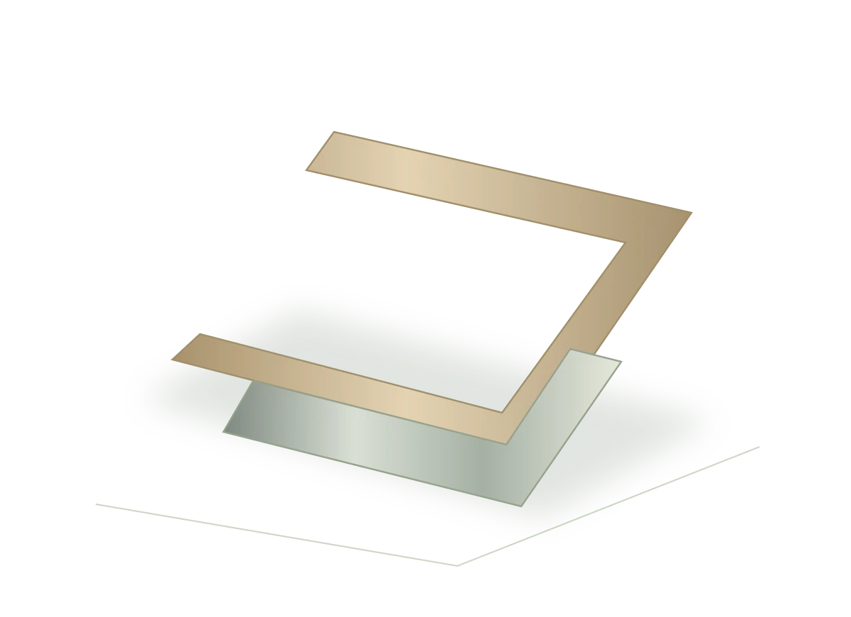
Schematic illustration · Final geometry is defined by approved project drawings.
Start with the detail.
- Wall panel joints
- Door and opening edges
- Feature lines and material transitions
Cross-section
State inside and outside dimensions, thickness and the faces that will remain visible. Identify fit-critical dimensions and the material the profile connects to.
Cutting schedule
List finished lengths, quantities, mirrored parts and angled cuts. Confirm whether delivery is in full lengths or installation-ready pieces.
Corners and protection
Show end caps, corner pieces and permitted joints. Agree finish direction, protective separation and part labels for delivery.
A clear scope.
A reviewable quotation.
Material, appearance and supply details are confirmed for each project.
| Material grade | 304 / 316 options reviewed against the project specification and installation environment. |
|---|---|
| Thickness & dimensions | Confirm against the approved drawing; no single default thickness or size applies. |
| Visible finish | Choose a CT10 reference or provide a physical sample for review. |
| Quantity & minimum order | State quantity per part or total area. Minimum quantities are confirmed for the actual design and finish. |
| Lead time & delivery | Confirmed after drawing, finish, quantity and packing requirements are reviewed. |
| Documents | Agree the material records, inspection evidence and destination documents required before order confirmation. |